Numeric and Boolean
Numeric
Controls
The first section typically encountered on the LabVIEW Controls palette is dedicated to numeric controls:
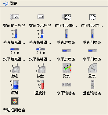
Despite varying appearances on the front panel, the controls within this column all represent numerical data types. The two controls in the upper right of the palette are designated for 'time', yet they too are a manifestation of numeric data. Other controls, located in different palettes, like drop-down lists and list boxes, also handle numerical data types.
The top two controls on this palette are the most frequently used numeric controls. They are simple in design, with the key difference being that the first is an input control and the second is an indicator (display control). Input controls are identifiable by their lighter background and include increment and decrement buttons – useful for touch screen-operated systems but less so for mouse and keyboard setups. Beyond these basic options, LabVIEW offers a variety of specialized numeric controls suited to different application environments and data representations. For instance, a liquid tank control might be used to depict oil storage levels in a factory setting, while a Gauge control could simulate a car's dashboard.
LabVIEW numeric controls also boast diverse settings and display options, many of which are accessible via the control's right-click menu. This includes configurations like setting the base and unit for data:
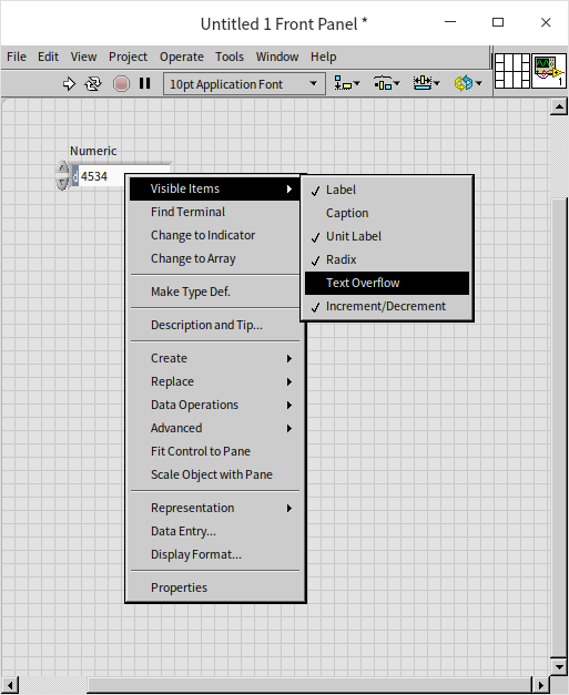
Beyond basic settings available through the right-click menu, LabVIEW numeric controls offer extensive customization through their properties dialog box. To access this, right-click the control and select "Properties":
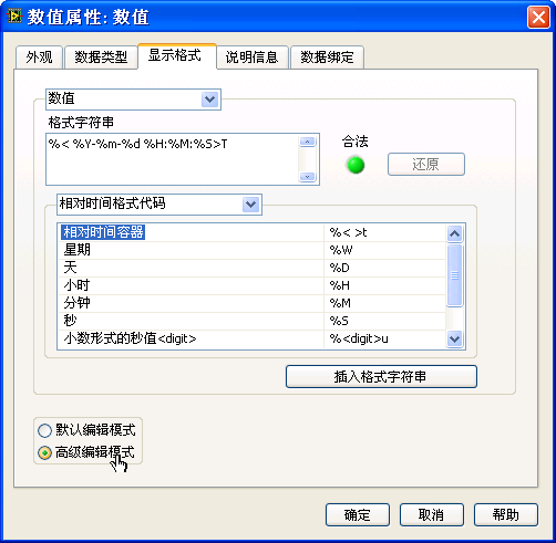
In this dialog box, you can adjust various aspects of the control, such as its state, size, and data range. The options are largely self-explanatory, indicated by their descriptive names. For instance, setting a numerical range helps prevent out-of-bounds errors during program execution, while choosing a specific display format can enhance data readability for users.
Within the display format section, there are multiple options for how data is presented. These include decimal, scientific, and engineering notations. For integer values, you can choose from different base systems, such as binary or hexadecimal. When representing time values, a single numeric display may not be intuitive. Instead, configuring the control to show dates and times in a familiar format like year, month, day, hour, minute, and second is more user-friendly.
Configuring the time display can be intricate, especially for custom formats. Initially, set the display type as "Absolute Time" (or "Relative Time") in the display format page, then use the "Advanced Editing Mode" to define the control's display format. For instance, inputting %<%Y-%m-%d %H:%M:%S>T in the "Format String" field allows the control to display a real number as "Year-Month-Day Hour:Minute:Second".
Here's how the real number "0.0" looks when formatted as absolute time:
In this context, a real number representing absolute time refers to the seconds elapsed since 1904-01-01 12:00am Greenwich Mean Time, or on the author's computer, 1904-01-01 08:00:00 Beijing time.
Constant
In LabVIEW, the behavior of numeric constants is intuitive and adapts to the input data. When you right-click on a numeric constant and access its shortcut menu, you'll notice the "Match to input data" option is selected by default. This default setting allows constants to automatically choose an appropriate representation based on the value you input.
For instance, inputting a positive integer like "34" into a constant will automatically set its type to an I32 integer, indicated by a blue icon . Conversely, if you input a decimal value like "34.3", the constant's type changes to a DBL real number type, represented by an orange icon
. To input the number 34 as a real number, you should enter it as "34.0".
This automatic data type selection feature is specific to numeric constants and is not available for numeric controls. In the case of numeric controls, you must manually select the desired representation to suit your specific needs.
Representations
In LabVIEW, numeric data can be represented in multiple ways to accommodate a variety of ranges and precision requirements. While numerical types like I32, U8, etc., can be considered as different representations of a single data type, they are often treated as distinct data types in text-based programming languages.
You can place a numeric control on the VI's front panel or a numeric constant on the block diagram. Both of these elements allow you to view or change the data representation via their right-click menus:
Consulting the LabVIEW Help index under "numeric value" will provide detailed explanations of each representation. The distinct icons for each representation indicate the varying lengths of data they encompass. As computers use binary representation where each bit can be either 0 or 1, with 8 bits making up 1 byte, the data length of each representation varies accordingly. The following table summarizes these lengths:
| Representation | Description | Bytes |
|---|---|---|
| EXT | Extended Precision Real | 16 |
| DBL | Double Precision Real Number | 8 |
| SGL | Single Precision Real Number | 4 |
| FXP | Fixed Point Number | Max 8 |
| I64 | Signed 64-bit Integer | 8 |
| I32 | Signed 32-bit Integer | 4 |
| I16 | Signed 16-bit Integer | 2 |
| I8 | Signed 8-bit Integer | 1 |
| U64 | Unsigned 64-bit Integer | 8 |
| U32 | Unsigned 32-bit Integer | 4 |
| U16 | Unsigned 16-bit Integer | 2 |
| U8 | Unsigned 8-bit Integer | 1 |
| CXT | Extended Precision Complex Number | 2×16 |
| CDB | Double Precision Complex Number | 2×8 |
| CSG | Single Precision Complex Number | 2×4 |
This table provides a quick reference to understand the varying lengths and types of numeric representations available in LabVIEW, assisting in choosing the appropriate type for a given application.
When selecting a data representation, it's crucial to ensure that it meets the program's requirements. For instance, the I16 data type supports integers ranging from -32768 to 32767. This range may be insufficient for even basic arithmetic operations like 300×300. Consider a simple exercise: create a new VI, place two I16 constants with a value of 300, multiply them, and display the result using an I16 numeric control. You will likely encounter an "overflow", because the result exceeds the maximum value that an I16 control can represent. Detecting such errors in large projects can be challenging.
The range of values that I64 can represent is significantly larger, reaching magnitudes of . However, even with such a range, it can only calculate factorials up to 20! . When a broader range of values is needed, or when dealing with decimal numbers, real number representations are used.
When considering the efficiency and storage requirements of a program, it's important to choose the appropriate data representation. Here are some key points to keep in mind:
-
Efficiency of Operations: Operations on real numbers are generally slower compared to those on integers. If the data in your program can be adequately represented by integers (such as counts of people, objects, etc.) and these values are not excessively large, it is preferable to use integer types instead of real numbers. This is especially relevant for values that inherently occur as integers in real-world scenarios.
-
Complex Numbers: Complex numbers consist of two real numbers representing the real and imaginary parts. Operations on complex numbers are slower than operations on simple real or integer types, so they should be used judiciously, mainly when necessary for specific computational requirements.
-
Impact on Storage: Although the difference in storage between types like U16 and U32 might seem trivial for individual data points (merely 2 bytes), this difference can accumulate significantly in large datasets. For instance, in an array with numerous elements, using U16 versus U32 can lead to substantial differences in memory usage. For an array with 1,000 elements, the difference in storage space between U16 and U32 representations is 2KB, which is manageable. However, for an array with 1 billion elements, the difference escalates to 2GB, which is substantial and can impact the overall performance and memory requirements of the program.
In summary, while longer data types offer a broader range and higher precision, they also require more memory and can slow down computations. Therefore, it's crucial to balance the need for precision and range with considerations of efficiency and storage, especially in large-scale applications or when handling extensive data sets.
Representations Conversion
Converting between different numerical representations is typically straightforward and doesn't usually require specialized functions. To convert a value, simply connect it via a wire to a terminal designed for another value type. This action triggers an automatic conversion to the new representation. Certain functions, like addition, are versatile and can handle data in various representations. When inputs in different representations are used in the addition function, it automatically adjusts the data with the smaller range into the one with a larger range. Consequently, the result adopts the representation with the larger range. To help programmers, a red dot (indicating a forced conversion point) appears at the site of the data representation change:
In most cases, these casting points don't hinder program functionality. However, they might occur inadvertently during coding and can pose hidden risks. For instance, if a programmer unintentionally uses a short data type for what was initially a long data type, it could lead to numerical overflow. To mitigate these risks, it's advisable to eliminate all coercion points (indicated by the red dot on the function). If a conversion is essential in your program, deliberately use the representation conversion function (found in the function palette under "Programming -> Numeric -> Conversion"). This approach helps prevent accidental numerical conversion errors:
Special Numbers
In LabVIEW, operations with integers and real numbers can produce special results under certain circumstances, notably when operations exceed the range of the data type or involve undefined mathematical operations. Here's how LabVIEW deals with these scenarios:
-
Integer Overflow: When an integer operation results in a value that exceeds the maximum or minimum value the integer type can represent, LabVIEW does not report an error. Instead, it wraps around within the representable range, leading to incorrect data. This behavior requires careful handling in programs to avoid misleading results.
-
Real Number Overflow: The maximum value a double-precision real number (DBL) can represent is approximately . Exceeding this limit does not cause an error in LabVIEW; instead, any number beyond this range is represented by the symbol Inf (positive infinity). Similarly, values less than the negative maximum are represented by -Inf (negative infinity).
-
Division by Zero: Unlike many programming languages where dividing by zero triggers an exception, LabVIEW represents as Inf. The rationale is that any non-zero number divided by zero approaches infinity. However, the case of is undefined and results in NaN (Not a Number), indicating an indeterminate value.
-
NaN in Operations: The NaN symbol is also produced in other undefined or indeterminate operations, such as operations involving a NaN value, adding +Inf and -Inf, dividing Inf by Inf, and taking the square root of a negative number in the real domain.
In the realm of complex numbers, operations that are undefined in real numbers can yield valid results. For example, the square root of -1 is a valid operation in the complex domain and should theoretically result in i (the imaginary unit). However, due to the limited precision of double-precision numbers, the result might include a tiny but non-zero real part due to computational errors. This illustrates the limitations in resolution and precision inherent in numerical representations.

These examples highlight the importance of considering computational errors, especially when comparing real numbers for equality. Even operations that should theoretically yield exact results may show small errors due to the approximations involved in floating-point arithmetic.
In summary, when working with numeric data in LabVIEW, it's crucial to be aware of how the environment handles special cases like overflows, division by zero, and the limits of numerical precision. This understanding is essential for writing robust and reliable programs that correctly handle edge cases and numerical anomalies.
Fundamental Funcitons
The primary functions and nodes for numerical data manipulation are found in the "Programming -> Numeric" section of the function palette:
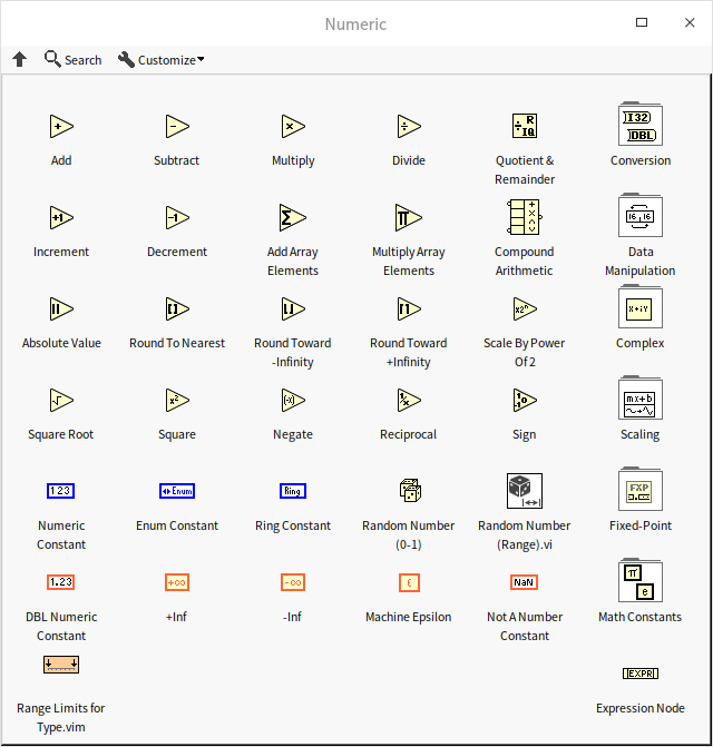
The design of these function nodes is intuitive, clearly representing operations such as addition, subtraction, rounding, reciprocal, etc. For more complex mathematical functions and VIs, refer to the Math function palette. Detailed descriptions of each function are available in the LabVIEW help documentation, and will not be reiterated in this guide.
Mathematical operation algorithms can be complex. If you're uncertain about which function palette contains the needed function, utilize the search feature. Click the "Search" button (marked with a magnifying glass icon) above the function or control palette to access the palette search:
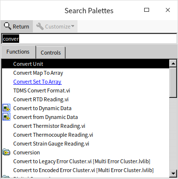
Type keywords into the search interface, then drag and drop your selected search result onto the VI block diagram or front panel. Double-clicking a search result will navigate you to its location in the palette, helping you remember where to find it in the future.
Many mathematical operation function icons are smaller, and their input terminals are closely spaced (like the subtraction function). If you mistakenly connect the input data wires to the incorrect terminals or wish to swap the positions of the two inputs, there's no need to delete and reconnect. Instead, use a more convenient method: hover the mouse over the input terminal of the function, then press the Ctrl key. The cursor will change to a scissor-like shape. Clicking the mouse at this point will swap the connections between the two input terminals, as shown below. This shortcut works for functions with two input parameters.
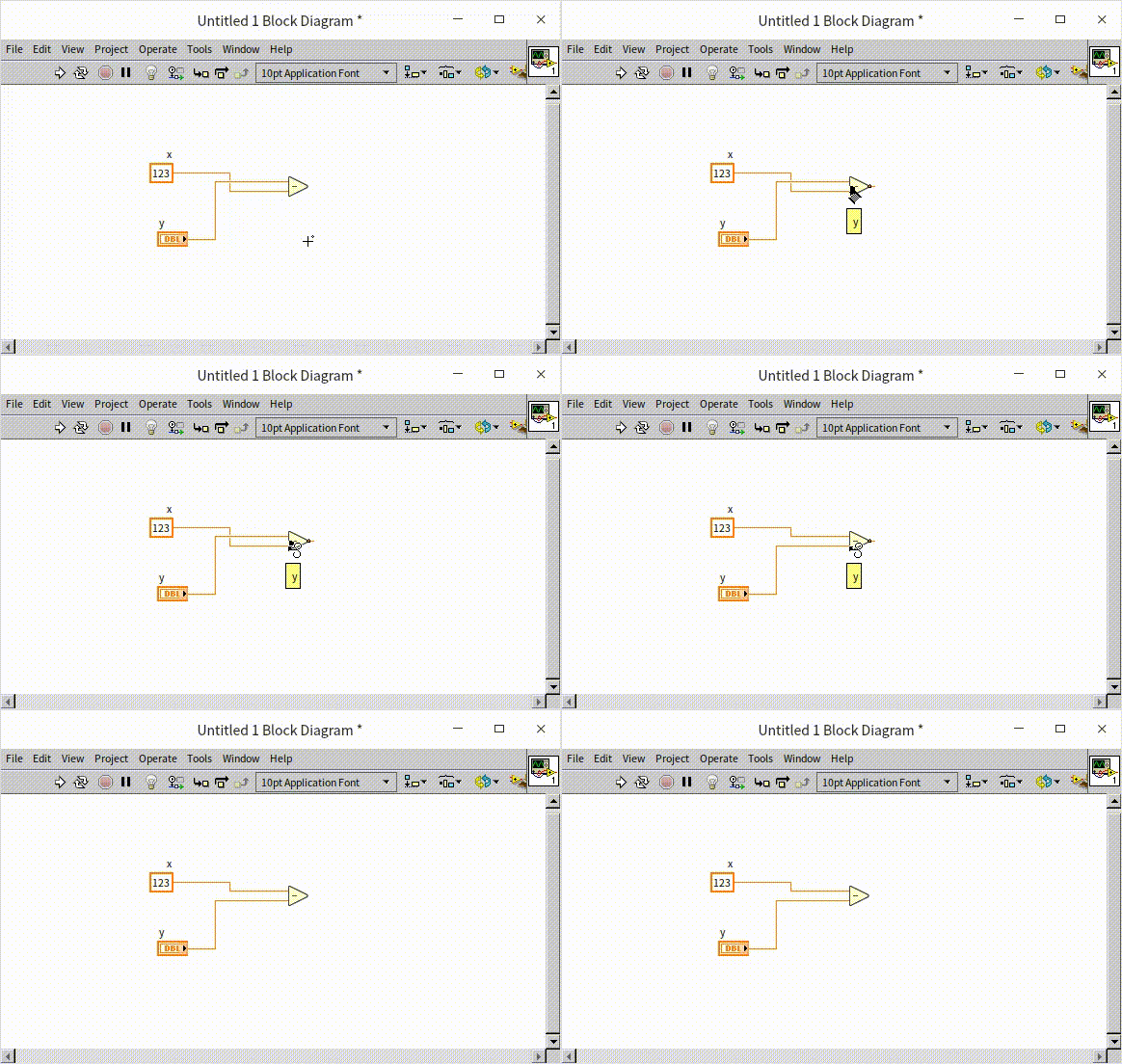
Expression Node
For straightforward arithmetic operations like addition, subtraction, multiplication, and division, basic function nodes are typically adequate. However, when dealing with more intricate numerical calculations, you might end up using numerous function nodes. This can lead to a cluttered arrangement with crisscrossing or cornered connections, which hampers readability and maintenance of the program. In such scenarios, other programming approaches, like expression node, become preferable.
Expression nodes are particularly useful for operations that involve a single input and output.
Take, for instance, converting Fahrenheit temperatures to Celsius. This can be achieved using basic operation functions. Yet, despite the simplicity of the operation, it might not be immediately apparent that it corresponds exactly to the familiar formula, requiring the reader to decipher it step-by-step. This is a limitation of graphical languages in representing pure mathematical computations. Text expressions, being in line with the format commonly found in textbooks and written materials, are more direct and understandable. In LabVIEW, expression nodes enable you to articulate operations using text, making the formula clear and intuitive, as illustrated in the lower part of the following figure:
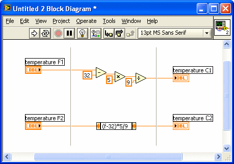
Another benefit of using Expression Nodes is their space efficiency on the block diagram, compared to basic arithmetic funcitons.
Expression nodes allow only one string to represent the input parameter, meaning they are suited for single-variable functions. In the example above, 'f' denotes the input parameter.
LabVIEW's online help documents the supported operators, functions, and expression rules for expression nodes. Both the expression nodes and the formula nodes (which will be discussed later) in LabVIEW borrow the syntax for mathematical expressions from C language. Thus, if you are familiar with C language, you can easily adapt to using these nodes without much additional help. For instance, +, -, *, / are used for basic arithmetic, ** for exponential operations, and sqrt() for square root calculations, among others.
Formula Express VI
For operations that require multiple inputs, the Formula Express VI is an ideal tool:
The intricacies and applications of Express VI will be explored in more detail in later chapters. For now, let's provide a brief overview of the Formula Express VI. Located under the "Math -> Scripts and Formulas" section of the Functions palette, this VI is easily accessible. When dragged onto the block diagram, it immediately displays a configuration panel resembling a sophisticated calculator, allowing for intuitive use with minimal learning required:
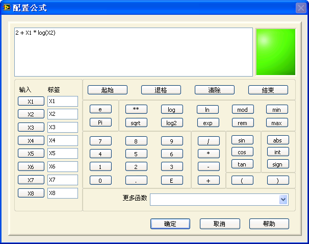
The Formula Express VI supports up to eight input data points but is limited to only one output data point. A notable drawback of this VI is its lack of transparency in expression visibility; the specific formula used is not directly visible on the block diagram. To view or edit the calculation formula, users must double-click the VI to open the configuration panel. This additional step may be a slight inconvenience for those who prefer immediate visibility of the formula on the block diagram.
Formula Node
For Multiple-Input-Multiple-Output (MIMO) or more intricate calculations, the formula node is a suitable tool. You can find it under "Programming -> Structure" in the Functions palette:
Think of the formula node as an advanced version of the expression node, equipped to handle multiple inputs and outputs. Its expression syntax is akin to C language, essentially functioning as a subset of C that focuses on basic mathematical operations. Those familiar with C language will find using formula nodes quite straightforward. However, for those without C language experience, a basic understanding of C syntax is beneficial for effectively utilizing formula nodes.
In a formula node, input variables don’t require a declaration within the node itself. For instance, the variables 'a' and 'x' in the above example have their types defined in the input control. Conversely, other variables within the node must be declared beforehand, adhering to C language syntax. For example, 'y' and 'temp' need an upfront declaration as 'int32' at the program's start.
When you first add a formula node, it appears as a blank gray rectangle. You need to write a text program, similar to C language code, within the node's frame. Then, by right-clicking the frame and selecting "Add Input" and "Add Output" from the context menu, you can incorporate input and output variables into your program. These inputs and outputs appear as small squares along the node's border—inputs on the left and outputs on the right. The variable names are written in these small boxes. This method allows for a structured approach to integrating complex mathematical operations within your LabVIEW program.
In algorithm implementation, textual expressions are often more intuitive and familiar, reflecting the way formulas and calculation processes are presented in textbooks and other written materials. Textual methods offer a clear, sequential display of all branches in programs with numerous selection structures. In contrast, LabVIEW's graphical interface can show only one branch at a time within a selection structure, requiring users to click through each branch to read the content, which can hinder readability.
Therefore, in programs involving complex mathematical operations, utilizing formula nodes can significantly enhance both readability and maintainability.
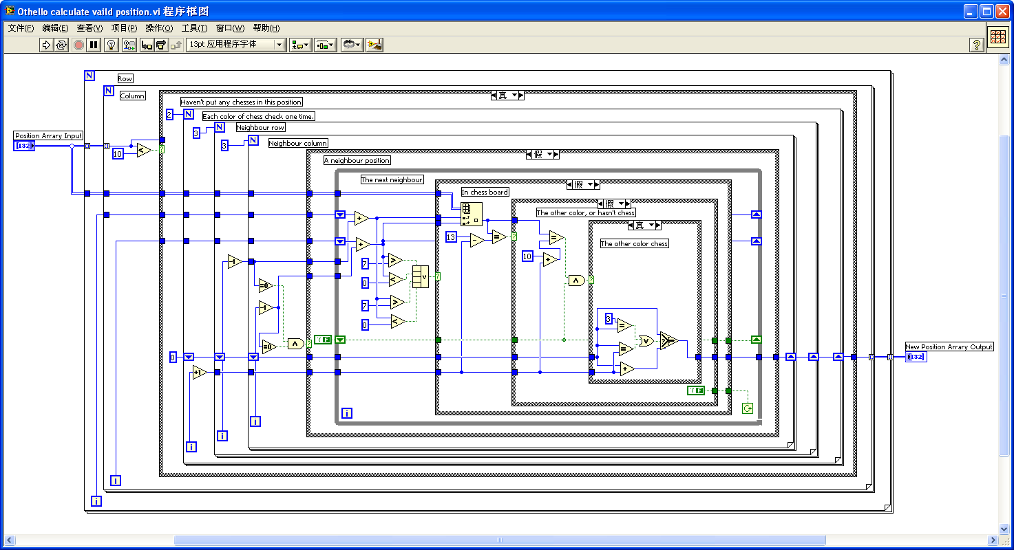
The image below is from a sub VI in a chess game program, designed to calculate the position of a movable piece. It involves simple numerical operations on a two-dimensional integer array but becomes complex due to multiple nested loops and selection structures, challenging readability. The specific functioning of this program isn't crucial for this discussion; it merely serves to illustrate the potential complexity of LabVIEW coding.
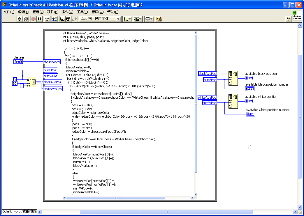
The next figure represents a block diagram of a similar subVI, but this one employs a Formula Node. For programmers with comparable proficiency in C language and LabVIEW, the program depicted here is more straightforward to comprehend. The code within the Formula Node is clearer and easier to understand.
However, there are some drawbacks to using formula nodes. For users without prior experience in C language programming, learning the syntax of the formula node can be time-consuming, introducing an additional learning curve.
Another limitation is that code within formula nodes cannot be breakpointed or debugged in the traditional sense. To ensure the accuracy of the code, it is advisable to first compile and debug it in a C language compiler. Once its correctness is verified, it can be implemented within the LabVIEW formula node. This step, while adding an extra phase to the development process, helps in maintaining the integrity and functionality of the code.
Units
In measurement and control applications, LabVIEW stands out for its ability to handle not just abstract numbers, but physical quantities with real-world significance. Consequently, LabVIEW's numerical controls and constants can be assigned physical units. To add a unit to a numerical value, right-click on the numerical control, select "Display Item -> Unit Label", and then enter the desired unit. Units are typically represented by their English abbreviations. If you're unsure of a unit's correct abbreviation, enter any character, right-click the unit label, and select "Create Unit String". LabVIEW will then display a dialog box listing all the units it supports.
LabVIEW automatically handles conversions between different units. For instance, to find out the number of days in two years, the following program can be used:
Assigning data of one type to a control of a different type, such as assigning an I32 type data to a string control, is a mistake. LabVIEW, like most programming languages, can report such errors during compile time. Additionally, LabVIEW checks for unit consistency in numerical data, applying even stricter rules: not only can real numbers and strings not be interchanged, but also two real numbers representing different physical quantities, like time and length, cannot be assigned to one another.
Therefore, when writing LabVIEW programs, it's beneficial to use numerical controls with assigned units. LabVIEW prevents connections that would mix incompatible units, such as time and length, thus helping to avoid errors in your program:
When it comes to operations between a physical quantity with a unit and a numerical value without one, some operations are permissible while others are not. For example, the numerical constant π has no unit. Calculating the circumference of a circle with a diameter of 2 meters, 2m * π, is allowed. However, adding two meters to π does not make physical sense and is not permitted.
LabVIEW's strict enforcement of unit consistency, while useful for preventing errors, can sometimes pose challenges. For instance, if you have created a subVI to calculate the sum of two time values, you cannot use this same subVI for summing length values due to the difference in units. To address this, LabVIEW introduces the concept of unit wildcards.
Unit wildcards allow you to write subVIs that are adaptable to various units. Represented by "1". If you need another subVI for different operations, you could use "$2" for its unit, and so on.
However, it's important to note that many of LabVIEW's built-in VIs don't incorporate unit wildcards. If you pass data with units directly to these VIs, LabVIEW will flag an error. In such cases, the workaround involves converting data with units to unit-less data before the calculation and then converting it back to unit-based data afterward.
The "Convert Unit" node (found under "Programming -> Value -> Conversion Function" palette) is used for this purpose. It can convert a pure numerical quantity to a quantity with a unit, or vice versa. For instance, to generate a random length between one and two meters, you could use LabVIEW's "Random Number (Range).vi". Since this VI doesn't support unit wildcards, a unit conversion is necessary:

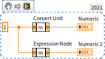
For more flexible direct unit-to-unit conversions, the "Cast Unit Bases" node under the same palette can be utilized. It's crucial to recognize that the appearance of the unit conversion node is identical to that of the expression node. Although they look the same and even had identical right-click shortcut menus in earlier versions, their functions are distinctly different. The two nodes in the program below may appear similar but yield very different outcomes:
Boolean
Conversion Between Boolean and Numeric
Boolean data is binary, representing only two states: "true" or "false". In theory, a single bit can suffice for these two values. However, desktop and laptop computers process data in bytes (8 bits), meaning these Boolean values are represented by a byte each. In this context, "false" is indicated when all bits in a byte are 0; any other combination signifies "true". The following program illustrates the conversion relationship between numeric and Boolean types:
Numeric comparisons yield Boolean results. For instance, comparing whether 2 is greater than 1 results in "true". However, special attention is needed when comparing real numbers for equality and dealing with special values.
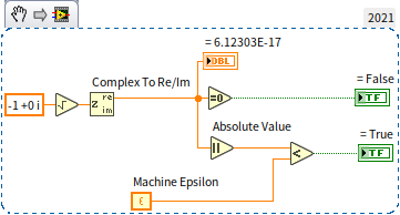
Real number comparisons should account for potential errors. Computers can only represent a limited range of numerical values, leading to approximations and errors. Generally, two real numbers are considered equal if their difference falls within a predetermined range. This error tolerance depends on the project's specific conditions and requirements. Running the same program on different computers may produce varying errors. For example, a direct comparison of whether the real part of is 0 yields "false" on the author's computer. On other computers, this judgment might be "true". To ensure consistent results across different systems, it's crucial to set an error range for equality comparisons. This approach confirms that the real part of is zero on any computer:
Is a value x definitively unequal to x + 100? While this holds in mathematical calculations and many programming languages, it's not always the case in LabVIEW. In LabVIEW, infinity is treated as equal to infinity, and any arithmetic operation involving infinity (addition, subtraction, multiplication, or division) results in infinity (or negative infinity):

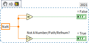
NaN (Not a Number) is unequal to any number, including itself. To check if a value is NaN, the "Not a Number/Path/Reference" function must be used:
Boolean Controls
Boolean controls in LabVIEW are visually represented in various styles, including switches, buttons, and light bulbs:
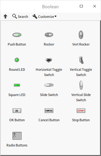
These controls not only mimic the appearance of real-world switches and buttons but also their behavior. They can be set to exhibit different mechanical actions. By right-clicking a Boolean control and selecting "Mechanical Action", you can access six types of mechanical actions as illustrated below:
The first two mechanical actions simulate switches. These controls toggle their state with each click: from on to off, or vice versa. The last four actions simulate buttons, which automatically revert to their default state after being pressed and released. Pressing a switch or button is a dynamic process, but a Boolean value only has two states. These six mechanical actions determine the precise moment when the control's value changes during the pressing action. The most intuitive setting for users is to select the first mechanical action for switch-type controls (changing the data value immediately upon mouse press) and the second option in the second row for button-type controls (emitting a pulse signal upon mouse release). A pulse signal means the Boolean value of the button control, originally False, briefly changes to True when the mouse button is released, and then immediately returns to False.
In many programs, buttons are used to trigger events for specific tasks. This concept is elaborated upon in the Event Structure section. Additionally, the usage of local variables and property nodes of the controls will be discussed in forthcoming chapters. Most controls, including Boolean ones, can be manipulated through their terminals or via their local variables and the "Value" property nodes. However, Boolean controls with trigger-based mechanical actions (the three types of mechanical actions in the second row) cannot use local variables or the "Value" property node.
Data Type Cast
Understanding Forced Type Conversion
LabVIEW includes a "Type Cast" function, located in "Programming -> Numeric -> Data Operations" on the function palette. This function allows data to be coerced into another type without altering the binary data in memory. This is similar to the cast operation in the C language.
Consider the following C language code, which coerces a double-precision floating-point number into an integer:
double dblNumber;
int64* intPointer= (int64*)(&dblNumber);
int intValue= *intPointer;
The equivalent function in LabVIEW would be as follows:
It's crucial to understand that forced type conversion differs from the conversions discussed earlier, such as converting data into different representations or using integers to represent Boolean values. Those conversions allow data to be expressed in various forms while retaining its inherent meaning, even though the data type and binary value in memory might change. For example, the data "13.4" can be represented as a 32-bit floating point number, a 64-bit floating point number, or even a string. These different forms store distinct binary data in memory, but to users, "13.4" consistently represents the same number.
Forced conversion, however, operates differently. In this process, the binary data recorded in memory remains unchanged, but the way users interpret this data changes significantly.
Consider the LabVIEW program that employs the "convert to 64-bit integer" function to transform the value 13.4. This operation results in the integer 13, where the essence of the data is maintained but its precision is reduced. It's important to note that the DBL (double-precision floating-point) representation of 13.4 and the I64 (64-bit integer) representation of 13 have entirely different binary content in memory.
During a forced type conversion, the I64 value corresponding to the DBL value 13.4 is actually 4623733147430603981. Both representations use 8 bytes in memory, with the binary sequence being: "0100000000101010110011001100110011001100110011001100110011001101." If this binary string is interpreted according to the storage rules of a double-precision real number, it conveys the value 13.4. However, when interpreted as an I64 integer, it translates to 4623733147430603981.
This example underscores the essence of forced conversion in LabVIEW: the underlying binary data remains constant, but its meaning significantly shifts depending on the chosen data type. While the original value is not altered at the binary level, its interpretation and thus its expressed value can change dramatically through this conversion process.
Purpose of Forced Conversion
The application of forced type conversion should be carefully considered, as it can significantly impact the meaning and interpretation of data. Binary data holds a specific meaning when expressed under a certain type. Changing this type might result in a loss of the original intent or significance of the data.
Consider the previously discussed program as an example. Imagine it's part of a testing application where the real number 13.4 represents a measured current temperature. If this value is forcibly converted to an I64 type value, becoming 4623733147430603981, its original meaning — as a temperature reading — is entirely lost.
Hence, forced type conversion is most meaningful and appropriate when performed between data types that maintain the same internal representation. When changing data types, it's crucial to ensure that the conversion maintains the data's original context and purpose. Otherwise, the result might be a numerical value that, while technically accurate in its new form, no longer conveys the intended information or meaning
Conversion Between Boolean and U8
The conversion between Boolean data and U8 (or I8) types is logical, as both are stored in a single byte in memory. This allows for straightforward casting between these two data types. The following two programs demonstrate methods for converting between numeric values and Boolean values, both achieving the same result. Conversion using Type Cast:
Conversion without using Type Cast:
However, it's important to note that if the data representation in these programs is expanded from a single byte to multiple bytes, such as using an I16 value for testing, the outcomes of the two programs will differ significantly. For multi-byte values like I16, it's still feasible to use functions to check if the value equals zero or to use selection functions to convert "true" and "false" conditions into different numeric values. However, the utility of cast type conversion diminishes in these scenarios.
The Boolean type occupies only 1 byte, so when a multi-byte value is converted into a Boolean type, the resulting Boolean value is determined solely by the first byte (the highest byte) of the multi-byte value. Therefore, even if a multi-byte value is not zero, its first byte might be zero. As a result, this kind of forced conversion usually lacks practical significance, especially in contexts where the full range of a multi-byte value is relevant to the data's meaning or application.
Conversion Between Time and Numeric
LabVIEW uses real numbers to represent time, but for more convenient manipulation of time data, it also introduces a specialized data type called "timestamp". Despite this, the core principle of recording time in seconds remains the same. LabVIEW employs two 64-bit values to store time information: the first 64 bits for the integer part of the seconds and the 2nd 64 bits for the fractional part. Although the total length is similar to an extended-precision real number, the format of representation differs.
Time can be categorized into two types: relative time and absolute time. Relative time indicates the duration between two moments, and in LabVIEW, it is recorded as the number of seconds between these points. Absolute time, on the other hand, specifies a particular moment in terms of year, month, day, hour, minute, and second. LabVIEW records absolute time as the number of seconds elapsed since 12:00 am Greenwich Mean Time on January 1, 1904, which is a standard starting point used by most software for timing.
For instance, if the relative time is 2 minutes, LabVIEW internally records this as "120.0". If the absolute time corresponds to the opening time of the 29th Beijing Olympic Games (8:00:00 pm on August 8, 2008, Beijing time), LabVIEW records it as "3301041600.0". This number represents the total seconds passed since 12:00 am Greenwich Mean Time on January 1, 1904, effectively making absolute time a specific form of relative time.
time values can be converted into numeric representations using the "Representation conversion" function. Conversely, numeric values can be transformed into time values using the "Convert to Timestamp" function: . The conversion between time in seconds and more conventional time units like years, months, days, hours, minutes, and seconds is facilitated by the "Date/Time to Seconds Conversion" and "Seconds to Date/Time Conversion" functions. An example of such a conversion is depicted in the following program:
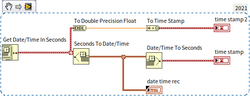
The results of running this program are as follows:
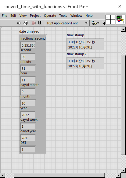
Understanding that a timestamp is stored in memory as 128-bit binary data—with the first 64 bits for the integer part and the last 64 bits for the fractional part—allows for additional manipulation. You can forcibly convert time data into a cluster of two U64 types. The integer part of the time can be directly displayed after conversion to U64. The fractional part can also be displayed after a simple conversion, as illustrated below:
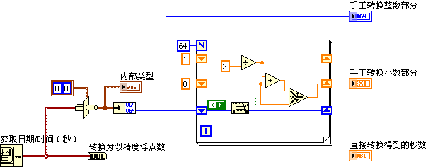
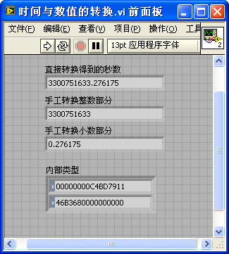
The results of this program demonstrate that the outcomes from forced data type conversion and the standard conversion functions provided by LabVIEW are consistent:
The exploration of data type coercion in this section is mainly intended to enhance understanding of how data is stored in memory in LabVIEW. However, in practical applications, it is advisable to use the conversion functions provided by LabVIEW rather than resorting to forced type conversion. Incorrect casting, particularly when the data structure is not fully understood, can easily lead to erroneous results. Therefore, standard conversion functions should be preferred for their reliability and ease of use.
Practice Exercise
- Living Room Area Calculation: You have a living room shaped as a rectangle, with dimensions of 22.5 feet in length and 12.5 feet in width. Write a VI that calculates the area of your living room in square meters.
- Target Sum VI: Develop a VI that takes four numerical inputs: x1, x2, x3, and a target value. Also, include a Boolean output named "result". The goal of this VI is to determine if any two numbers among x1, x2, and x3 can be added together to equal the target value. For instance, if x1=3, x2=5, x3=7, and the target is 8, then "result" should be True because 3+5 equals 8. Conversely, if the target is changed to 2 while keeping x1, x2, and x3 the same, the "result" should be False, as no two numbers among x1, x2, and x3 add up to 2.