State Machine
Loop with Embedded Case Structure
The loop with an embedded case structure is a composite structure, characterized by nesting a case structure inside a loop. This pattern is frequently used in LabVIEW programming.
Imagine you need to develop a test program that comprises several test tasks, such as Task A, Task B, etc. The program is required to sequentially perform each of these tasks. This scenario typifies a sequential structure program, and it can be approached using methods suited for creating such a structure:
However, if the program requirements become more intricate, a simple sequential structure may lack the necessary flexibility. For instance, suppose there are various products to be tested, each following a different testing sequence. Some products might need to undergo tasks ABC, while others require the sequence CDA. Writing different test programs for each product type is possible but leads to high maintenance due to the sheer number of distinct programs.
A more efficient strategy is to input the test task sequence into the program. The program then performs the test tasks according to the user-specified sequence each time. This can be achieved with a loop that incorporates a case structure:
In this setup, the "Task Queue" is ideally an input control, allowing users to select a group of test tasks on the main interface to change its input value, thereby bypassing the need to alter the program. However, for illustrative purposes, it is shown as a constant in this example. The “Task Queue” is an array with its elements arranged in the execution order of the tasks. As the program runs, the loop takes one task from the “Task Queue” in each iteration. The case structure then navigates to the appropriate branch based on the task's name, executing it accordingly.
Single-State Transition
Consider a scenario where the testing program's logic is more intricate, for example, where the choice of the next test task depends on the outcome of the current one. In such cases, the condition for each iteration in the loop is determined only after the completion of the preceding one. We can enhance the program as follows:
The program initiates by designating a starting task. Once the initial task is processed by the conditional structure, the next task is set based on the outcome of this task. A 'while loop' is employed here due to the unpredictability of the number of iterations required. Additionally, the conditional structure includes an "End Test" branch, responsible for exiting the while loop by transmitting a “true” value to the loop's stop condition terminal.
This refined structure is known as a state machine. In a state machine, there are several defined states, but it exists in only one state at any given moment. It transitions to a different state in response to certain events or data inputs. In our program, each branch of the conditional structure signifies a state, with each loop iteration leading to a transition to another state.
Given the frequent use of state machines, LabVIEW includes a state machine VI template. This template can be accessed from LabVIEW’s startup screen:
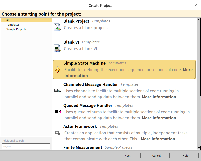
Alternatively, you can find it by opening the "File -> New" menu in VI, selecting “VI -> From Template -> Framework -> Design Pattern,” and then choosing the “Standard State Machine”:
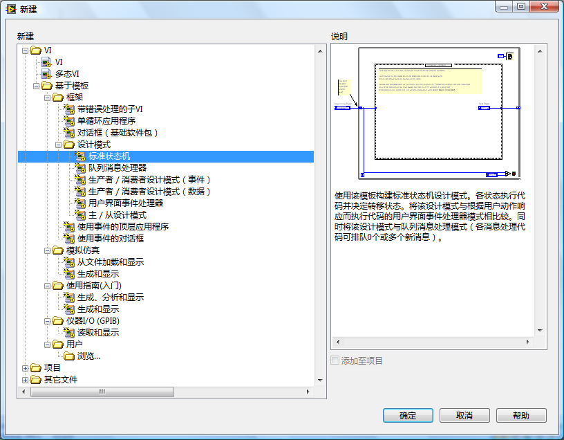
This template streamlines the process of setting up state machines in LabVIEW, offering a structured and efficient approach to managing complex, state-dependent logic in your programs.
Multi-State Transitions
In the previously showcased state machine, each state is only able to determine its immediate successor before it concludes. However, real-world programs sometimes require the ability to decide on several future states based on current data after executing a branch. Implementing this more complex functionality calls for the use of queues.
A queue is a data structure designed to hold multiple elements of the same type. Its behavior resembles a queue of customers waiting in line, where the first person to join the queue is the first to be served and leave. Similarly, in a data queue, the elements follow a first-in, first-out protocol – the earliest element added to the queue is the first to be retrieved. In LabVIEW, functions for managing queues are located in “Programming -> Synchronization -> Queue Operations.” Unlike other common data structures like arrays, maps, and sets, LabVIEW's queues were initially conceived for transferring data between threads rather than for data storage. However, this characteristic doesn’t preclude their use in managing state transitions in our context. More comprehensive details on queues will be presented in the Pass by Reference section.
The enhanced state machine program utilizing queues is depicted below:

The process starts by creating a queue to hold the states the program needs to transition through. The initial state is added to this queue before the loop begins. During each loop iteration, the upcoming state is retrieved from the queue, guiding the selection of the conditional structure's branch. Upon completing a branch, the program adds the multiple subsequent states for transition back into the queue, effectively queuing up the next stages of the state machine.
Effective Use of State Machines
State machines are an effective way to represent the operational processes of many programs. In LabVIEW programming, a common approach is to first draft a state diagram for the program and then base the code development on this diagram, using LabVIEW’s pre-established templates. This strategy has proven to be a highly efficient method for program design and development, making state machines a popular pattern in LabVIEW.
However, state machines come with certain drawbacks:
First, the heart of a state machine is its conditional structure. This structure, along with event structures and cascaded sequence structures, shares a limitation: they can only display the code of one branch at a time, which hinders the program's readability.
Second, when dealing with large-scale programs that handle dozens or even hundreds of states, the resulting state diagram can become exceedingly complex. Excessive branches in a LabVIEW conditional structure also significantly diminish the readability and maintainability of the program. For such extensive applications, it becomes necessary to modularize the states and create different hierarchical levels. For example, in a product manufacturing program, the top-level might alternate between states like “Design,” “Production,” and “Testing.” Within the “Testing” state, there could be several sub-states, such as “Test Keyboard” and “Test Screen.” Managing these varied state levels in separate VIs helps prevent any single VI from becoming overly complex.
In the early days of LabVIEW, prior to the introduction of event structures, state machines were commonly used to handle user interface processes. However, with the introduction of event structures, they have largely supplanted conditional structures in UI-related programming. The loop event structure pattern, discussed in the Event Structure section, can be viewed as a type of state machine. However, for UI-related tasks, using events for state transition control is more practical.
In the wider realm of computer software, state machines have extensive applications in areas such as lexical and syntactic analysis, regular expression matching, and mathematical expression computations. We previously showcased a VI capable of evaluating mathematical formulas in string format:

Now, let's explore how to implement similar functionalities with a state machine approach. Given the complexity of “Eval Formula String.vi,” we'll use a simpler example for demonstration purposes, focusing on processing and calculating mixed arithmetic operations involving only positive integers.
Program Requirements
Firstly, let's clarify the constraints and objectives for our program. We aim to develop a program that calculates arithmetic expressions presented in string format. The program must adhere to these requirements:
- The input is a string consisting solely of digits (0-9) and the four basic arithmetic operators
+-*/. Any other characters will result in an error. - All numbers in the input must be positive integers, with any deviation causing an error. The result might be a real number, especially due to divisions.
- Multiplication and division take precedence over addition and subtraction.
- For demonstration purposes, we avoid using advanced string processing functions like search or find. When converting from string to number, conversion must happen one character at a time.
An example calculation would be 1+2*3-4/5-6, which should yield a result of 0.2.
Designing the Data Structure
In this problem, we can't process the string from left to right and compute outcomes whenever two numbers and an operator are encountered. This is because multiplication and division have a higher priority than addition and subtraction. Therefore, upon encountering an addition or subtraction operator, we need to temporarily store the data and operator, and later decide when to perform the calculation. This situation, having only two priority levels, could be managed with two shift registers to save the required data and operators. However, more complex scenarios, like handling expressions with brackets, involve numerous priority levels, making a mere pair of shift registers insufficient. To demonstrate a more versatile solution, we will utilize a stack data structure to store both data and operators, using separate stacks for each.
A stack is akin to a handgun's magazine: data is loaded into the stack like bullets into a magazine, with the first-loaded being the last out, following a last-in, first-out principle.
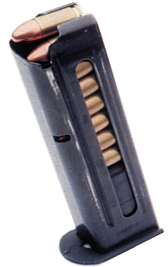
While LabVIEW doesn't feature a specific stack data structure, its queues can operate bidirectionally, allowing data entry from either end. In a standard unidirectional queue, data enters from the left and exits from the right. However, in LabVIEW, queues can also accept data from the right end. By ensuring data only enters and exits from the right, we can use these queues as stacks.
As for the input string formula, to facilitate subsequent operations, we'll store it in a character queue.
The program’s approach is as follows: it sequentially reads data and operators from the string, storing them in the stack initially. It then continues reading until the next operator is encountered, at which point it assesses whether the previously stored data and operator can be computed. If computation is feasible, it stores the result and proceeds with the next segment.
Designing the State Diagram
For the same problem, various state diagrams can be conceptualized. You could create more states for simplifying tasks within each state, or have fewer states with more complex functionalities. Let’s consider breaking down the problem into the following six distinct states:
- Init (Initial State): In this initial state, if the next input character is a digit, the state machine transitions to "Construct Number". If the next character is empty, indicating the end of input, it moves to the "Calculate" state.
- Construct Number: This state is responsible for combining multiple numeric characters into a complete integer. If the next input is still a digit, it stays in this state. If it’s empty, it shifts to "Calculate". If it encounters a "+" or "-", it proceeds to "Check Stack 1", and for "*" or "/", it goes to "Check Stack 2".
- Check Stack 1: Here, the top operator of the stack is examined. If the stack is empty, the machine moves to the "Push" state. If not, it transitions to "Calculate".
- Check Stack 2: The presence of two “Check Stack” states is due to the varied precedence of operators. This state checks the top operator in the stack. If it’s empty or a "+" or "-", indicating calculation isn’t yet possible, it heads to "Push". For "*" or "/", it moves to "Calculate".
- Push: This state involves pushing the recently read data and operator onto the stack, then reverting to the "Initial" state.
- Calculate: The most intricate state, it first inspects the operator stack. Absence of any operators signals the program’s end. If operators are present, one operator and two values are popped from the stack for calculation, and the result is pushed onto the data stack. Post this step, if the program continues, the next state is determined based on the forthcoming input: for "+" or "-", it transitions to "Check Stack 1"; for "*" or "/", it shifts to "Check Stack 2"; and if the input is empty, it stays in "Calculate".
The state diagram for the aforementioned structure is illustrated below:
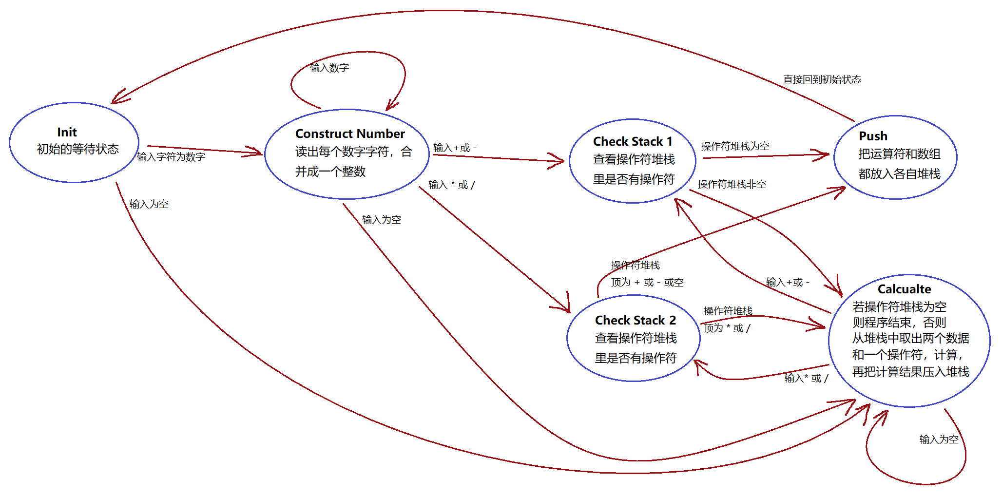
Segmenting the problem into six states provides a thorough breakdown for this relatively straightforward problem. This approach ensures that each state is tasked with only one specific function. Alternatively, a reduction in the number of states could be considered. For instance, the "Push" state, which transitions directly without any condition, could be merged with the following state. Similarly, the two "Check Stack" states could be unified, necessitating internal checks and distinct handling based on operator priority within that unified state.
Programming the Application
Given the simplicity of the task, we haven't utilized LabVIEW's provided templates, but our program's structure aligns perfectly with them. The first step is to create a custom enumeration type control that lists all the state names, aligning with the previously discussed states:
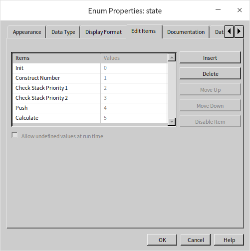
The heart of the program is a classic single-state transition state machine, primarily revolving around a conditional loop structure, with auxiliary code on either side for initialization and resource closure:
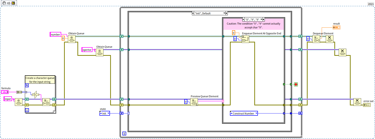
On the bottom left of the program, a small loop structure is dedicated to converting the input string into a character queue. This setup simplifies subsequent operations. Two wires extending across the conditional loop structure represent two stacks - the upper one being the data stack and the lower one, the operator stack. Each branch inside the conditional structure follows a similar logic: completing its own tasks first by processing data and then determining the next state.
The displayed branch is for the "Initial" state. When encountering a numeric character in the input, the program transitions to the "Construct Number" state. It also inserts a value of 0 into the data stack. This stack is used not just for storing final data but also for interim values during number construction.
It’s important to note that when using string data as the input condition for the conditional structure, the condition "0".."9" doesn't capture the character "9". This exception needs to be specifically addressed, which might be considered a bug in LabVIEW. Further details can be found in the String section.
Below is the block diagram for the "Construct Number Data" process. The program initially retrieves a previously processed digit from the stack, adds a new digit to it, and then pushes the result back into the stack:
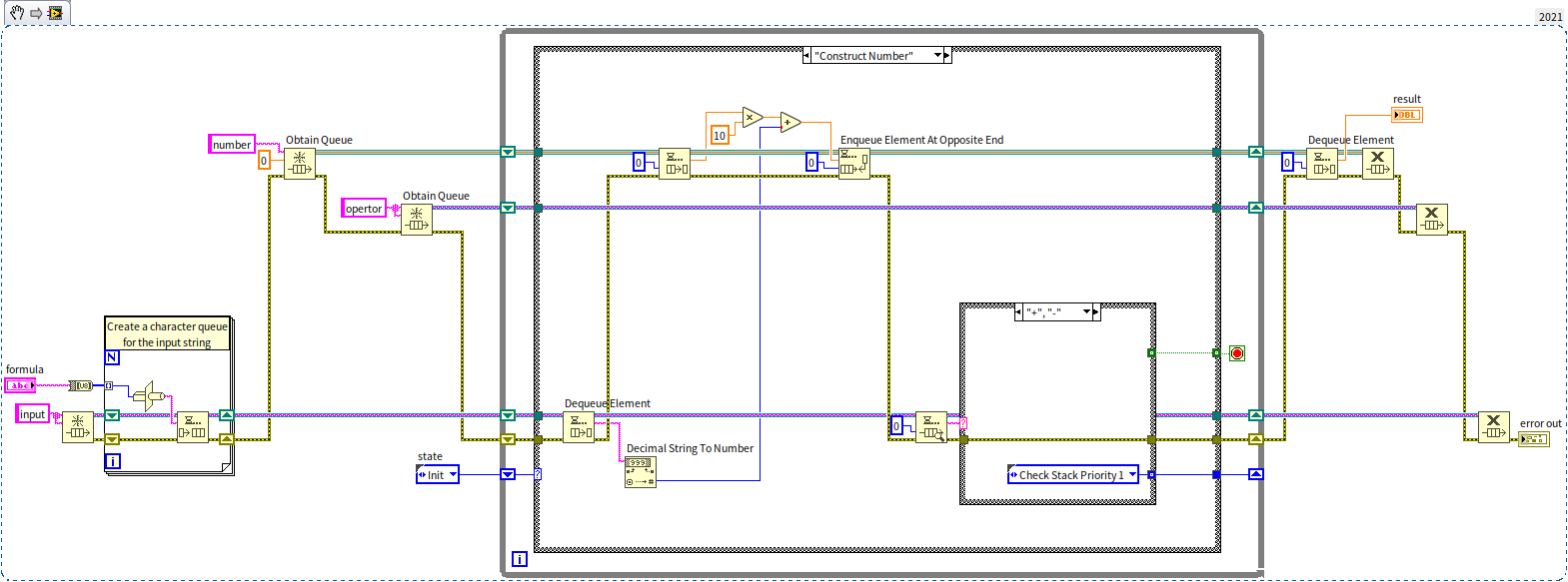
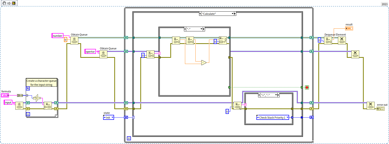
A slightly more intricate state is "Calculate". Its algorithm is consistent with earlier descriptions. For instance, the shown branch deals with addition: it pops an addition operator and two values from the stack, conducts the addition, and then pushes the result back into the data stack. Finally, the program transitions to a new state based on the next input character:
Practice Exercise
- Create a VI where the front panel features three lights: red, yellow, and green, mimicking the sequence of traffic signals. The lights should have four different states: only green lit, green with flashing yellow, only yellow lit, and only red lit. Each light should remain in its state for a set duration before transitioning to the next, in a continuous loop.