Event Structure and UI
Event Structure
Event structures are similar to case structures. Their key difference lies in their operation: event structures execute a specific branch of code based on the occurrence of an event.

When an event occurs, the event structure detects it automatically, eliminating the need for data lines to relay the event. The event label at the top of the structure indicates the event associated with the current branch. In addition to identifying the event, the structure also captures related information, such as the time of the event and the control on which it occurred. This information is accessible from the event data node located on the inner left side of the event structure.
Classifying Events by Source
In LabVIEW programs, events are classified into six major categories based on their origin. These categories are listed in the "Event Sources" section of the "Edit Events" dialog box. Each category includes specific event-generating VIs or controls, along with other sources of events. The details of each event for a given source are displayed in the "Events" section on the right. To set up a new VI, place some controls on its front panel, and then add an event structure to the VI's block diagram. Right-click the border of the event structure and select options like "Add Event Case" or "Edit Events Handled by This Case" to open the Edit Events dialog box.
LabVIEW 8.6's Edit Events Dialog Box:

These six main categories of events are:
<Application Events>
Application events primarily reflect changes in the overall status of the application. These include scenarios like whether the program is closing, if there's a change in the status of the help window, or occurrences of timeouts.
A prime example within the event structure is the default "Timeout" event, which falls under application events. Its default state is "Never Timeout", indicating that, without any input data, the program will never trigger this default timeout event branch. However, if a value representing milliseconds (n) is input to the timeout terminal (identified by an hourglass icon at the top left corner of the event structure), the event structure will automatically execute the code within its timeout handling branch every n milliseconds, as demonstrated in the following program:

<This VI Events>
These events are specific to changes in the state of the current VI (Virtual Instrument). Examples include adjustments to the size of the current VI's front panel or selections made from its menu.
Dynamic Events
Dynamic events are designed to manage events that are either user or dynamically registered within the program. These will be explored in greater depth later in the text.
Pane Events
Pane events relate to activities associated with a particular pane, like a mouse entering or exiting the pane area.
By default, a VI's front panel is considered a single pane. However, this can be modified by selecting "Modern -> Layout -> Horizontal (Vertical) Split Bar" from the control palette:

Dragging the split bar onto the VI's front panel allows for the division of the panel into multiple panes. For example, the front panel in the image below has been divided into left and right sections by a vertical split bar. Each pane operates as if it were an independent front panel, capable of housing its own set of controls.

Right-clicking within a pane doesn't bring up pane configuration options, as this action opens the control palette. Pane-specific menu options, such as altering display modes or creating property nodes, are only accessible by right-clicking on elements like scroll bars or split bars.
Split Bar Events
Events associated with the split bar, such as when a user drags the split bar, fall into this category.
Control Events
This category includes all events related to user interface controls, for instance, when the value of a control changes. This is one of the most commonly managed types of events.
Event Editing Process
Unlike case structures where condition labels are directly written, event labels in an event structure require editing through the Edit Events dialog box.
To access this dialog box in the event structure, right-click and select options like "Add Event Case", "Copy Event Case", or "Edit Events Handled by This Case". This action brings up the Edit Events dialog box, as depicted below.
Edit Events dialog box in LabVIEW 2021:

When editing events, begin by selecting an event source from the "Event Sources" column, such as a particular control. Next, in the "Events" column, choose the specific event generated by that source which needs to be handled. For example, you might select the "Value Change" event under the "Switch" event source. The chosen event then appears in the "Event Specifiers" column.
A single event handling branch can manage multiple events. To add different events to the event label of this branch, click the plus sign located either below or, in some versions, to the left of the "Event Specifiers" column. This allows for the inclusion of additional events that the branch can process.
At times, a single user action can trigger the same event from multiple sources. For example, clicking a mouse on a "Switch" control on the front panel can cause both the "Switch" control and its containing pane to emit a "Mouse Down" event.
However, LabVIEW emits these events in a specific sequence:
-
Keyboard-related events, such as key presses and releases, only occur on the control that is currently selected (the one responding to keyboard operations).
-
Mouse-related events, like mouse presses and releases, follow an outside-in sequence. In the mentioned example, when clicking on the "Switch" control within a pane, the pane's "Mouse Down" event occurs before the "Switch" control's "Mouse Down" event. To give a more complex example: in a pane that has a tab control, which in turn has a cluster control containing a Boolean control, clicking the Boolean control would trigger the events in this sequence: "Mouse Down" event of the pane, "Mouse Down" event of the tab control, "Mouse Down" event of the cluster control, and finally, the "Mouse Down" event of the Boolean control.
-
Value change events are emitted in an inside-out order. If a cluster contains a Boolean control, for instance, a value change in the Boolean control will trigger events in the following sequence: the "Value Change" event of the Boolean control, followed by the "Value Change" event of the cluster control.
Below is an image of a very simple program. It has just a "Stop" button on its front panel and a single event structure in its block diagram. This event structure has only one branch, designed to handle the "Value Change" event of the "Stop" button.

When this VI is run, the program pauses at the event structure, awaiting an event. This particular event structure is configured to only respond to the "Value Change" event of the "Stop" button. Other interactions, such as mouse clicks or key presses, won't affect the program's execution.
Upon the user clicking the "Stop" button, the "Stop" Boolean control changes its value, generating a "Value Change" event. The event structure captures this event and immediately processes the branch handling the "Stop" control's value change. Once this branch is executed, the program concludes.
Differentiating Events by Timing of Occurrence
LabVIEW events can be classified based on the timing of their occurrence into two types: notification events and filter events.
Notification events are issued by LabVIEW after it has processed a user action. For instance, if a user changes the value of a string control using the keyboard, LabVIEW emits a "Value Change" notification event after updating the control's value. This allows users to implement code within the event structure to respond to the event, carrying out relevant actions following the "Value Change".
Filter events, in contrast, are issued by LabVIEW before processing a user action. If an event structure contains a branch to handle this type of filter event, LabVIEW will first execute this branch. The subsequent default action for the event depends on the instructions returned from that branch of the event structure.
Filter events can be easily identified by their labels, which have a question mark appended, such as in the "Key Down?" event.
The sequence is generally as follows: a user action triggers LabVIEW to issue a filter event; the code within the filter event's frame executes; LabVIEW then decides whether to perform its standard handling based on the returned instructions; and finally, the notification event is issued.
For example, let's consider a scenario where a string control is the active element on the interface. When a user presses a key, LabVIEW immediately issues a "Key Down?" event. If the program's event structure includes a branch for this event, LabVIEW executes it. In this branch, users can modify the key value or direct LabVIEW to disregard the action. If LabVIEW is not instructed to ignore the action, and once the event branch concludes, LabVIEW carries out the default "Key Down" process, displaying the character associated with the key in the string control. After finishing this default action, LabVIEW generates a "Key Down" event.
Here’s a practical example: a program with an interface that includes a string control for entering phone numbers, which should only consist of digits and hyphens. The control does not react to other key presses.
In this program, the "Key Down?" event is utilized. When this event occurs, the program first checks the type of key pressed. If it's a digit or a hyphen, LabVIEW will display the character represented by the key. Otherwise, LabVIEW is instructed to forgo its default response to the action. The program appears as follows:

The program can identify the character represented by the pressed key in ASCII format from the event handling branch's data node. The code then determines if the key is a digit or a hyphen, and this decision, when reversed, is passed to the "Ignore?" return node. The program uses this to decide whether to bypass the default handling of the action. As a result, when users input non-digit characters, LabVIEW skips processing these keystrokes, allowing the "Enter Phone Number" control to only receive digits and hyphens.
If multiple event structures are present in a single VI's block diagram, notification events are sent to all structures simultaneously when they occur. All related event structure branches process the event in the predefined order. Conversely, filter events are sent only to a specific event structure branch; after processing, the event is then sent to another structure.
This reveals that having several event handling structures in a single VI can lead to complex and challenging operational logic, severely impacting the readability and maintainability of the VI. Thus, it's generally best to avoid using multiple event structures in the same VI. In fact, a single event structure per VI is typically adequate for handling all events.
Using Event Structures
In most cases, programs are designed to handle more than just a single event. They typically need to respond to a variety of events occurring throughout their operation. As a result, event structures are often placed within a while loop. This setup, which encloses an event structure within a while loop, is known as a "looping event structure". An example of this can be seen in the program shown in the previous image, which utilizes a looping event structure.
Event structures are used independently only in very specific, rare scenarios. For example, a simple dialog box might only need to wait for the user to click an "OK" button before closing, without responding to any other events. In such instances, a single event structure can adequately fulfill the program's needs.
Let's reconsider a program we discussed earlier in the "Keeping a VI Running" section:

This program is inefficient. It's programmed to perform an addition every 200 milliseconds and update the "Meter" display control. However, most of the time, the values of the two input controls don't change. This means that the majority of the addition operations and the updates to the display control are essentially unnecessary. At the same time, increasing the interval between calculations is not ideal, as it would result in a noticeable lag in the display control's updates following changes in the input controls.
A more efficient approach is to have the program remain idle until the value of any input control is updated, and then promptly carry out the calculation and refresh the display control. A looping event structure is perfectly suited for this purpose. The revised program, using a looping event structure, is shown below:

The primary event branch in this setup is the "Knob, Dial: Value Change" event. The program operates as follows: It begins with the while loop, which enters its first iteration, running the code within, namely the event structure. Since no event requiring attention has occurred yet in the structure, the program stays in a waiting state. This waiting state doesn't consume system resources. When the value of the "Knob" or "Dial" changes, the program promptly runs the "Knob, Dial: Value Change" event handling branch, performing the addition and updating the display control efficiently.
After processing this event branch, the program exits the event structure. The default "False" value is then passed to the conditional terminal of the while loop, prompting it to continue with the next iteration and re-enter the waiting state.
The event structure also needs a branch to handle the "Stop" button's "Value Change" event. When the "Stop" button's value changes, its "True" value is sent to the while loop's conditional terminal, leading to the termination of the loop and the end of the program:

It's crucial to place the terminal of the "Stop" button within the appropriate branch of the event structure in the program. If the "Stop" button is situated outside the loop structure, and only a "True" constant is used in the event structure’s branch that handles the "Value Change" event of the "Stop" button, as demonstrated in the image below, will the program still operate effectively?

Normally, a button is expected to automatically revert to its original state after being pressed. However, in LabVIEW, when a button's mechanical action (refer to the Boolean Controls section) is set to emit a pulse signal, the button's data must be read for it to reset to its original state. Thus, positioning the "Stop" button outside the loop structure is generally not problematic, as the program ends once this button is pressed, and its resetting is not critical. However, if there are other buttons in the program, it's important to remember that if the button's data is not read within an event branch, its state will not reset. For example, in the program segment below:

In this scenario, the "OK Button" is initially set up as a button, but its placement outside the loop means that its state can't automatically reset, causing it to act more like a switch:

Buttons set to generate a pulse signal (the first two mechanical actions on the second row of the mechanical action menu) only produce a "Value Change" event once per press. The button's release, although it changes its value, does not trigger a corresponding "Value Change" event. As a result, in the program shown here, the value of the control "NewVal" remains perpetually true.

So, is it feasible to directly use the "Stop" control to manage the conditional terminal of the while loop within a looping event structure? Consider the program illustrated in the following image:

Let’s break down the workflow of this program: When the program is in a waiting state for an event, it will remain in that state until an event it can handle occurs. If the Stop button is pressed during this time, although its value changes, the absence of an event that the structure can handle means the program continues to wait. The program then gets stuck at the event structure and doesn't end the loop as anticipated. Therefore, to effectively exit this looping event structure, the "Value Change" event of the "Stop" button should be used.
Looping event structures are particularly well-suited for interface programming, hence they are one of the most common programming models in LabVIEW.
Dynamic Events
Initially, when you open the Edit Events dialog box, you'll find that the section for dynamic events is empty. This is because dynamic events are only accessible after being registered. The nodes associated with dynamic events are located under "Programming -> Dialog & User Interface -> Events" in the subpalette.

The "Register For Events" node is used to register events. This node can handle two types of events: those generated internally by LabVIEW, including all application events, VI events, pane, split bar, and control events we've discussed before, as well as user events.
First, let's look at the LabVIEW-generated events. These events are available for direct selection in the Edit Events dialog box. With the exception of the "Dynamic" category, events that can be selected directly in this dialog are classified as static events. Static events are limited to those emitted by objects within the same VI. For example, if a VI’s front panel includes a Boolean control, its block diagram’s event structure can directly add a branch to manage events associated with this control. However, in complex programs that make extensive use of subVIs or dynamically call other VIs (as detailed in the Loading and Running SubVIs section), there might be cases where one VI's event structure needs to handle events from a control in another VI. For instance, a Boolean control might be on the interface VI, but the event handling code is in a subVI. Obviously, the subVI won’t contain this control, so it can't set up an event branch for it in its Edit Events dialog box. LabVIEW addresses these scenarios with dynamic events. To leverage dynamic events, the control must first be registered in the event structure of its respective subVI.
To register an event, you first create a reference node for the control generating the event (more on this in the Pass by Reference section). Connect this reference node to the "Events" labeled event source under the "Register For Events" node, click on the event source, and select the desired event from the pop-up menu. Then, transmit the "Event Registration Refnum" generated by the Register Events node to the event structure's "Dynamic Event Terminal" to complete the registration.
Explaining this process in text can be complex, so let's clarify it with an example. Consider a VI where clicking the mouse on the VI panel displays the mouse's coordinates, and all events are processed in a subVI. The interface of the main VI appears as follows:

Our objective is that when the user clicks on the VI panel, the "Coordinates" control shows the mouse's position, and when the "Stop" button is clicked, the program terminates. As the main event handling code for this program is intended to be executed within a subVI, the block diagram of the main VI is relatively straightforward: it simply needs to pass the necessary data to the sub-program:

For the program to use a subVI to monitor and control the main VI's controls, there needs to be a way for the subVI to find and manipulate the main VI’s controls. In LabVIEW, this is achieved by generating a "reference" for the controls. Those who have experience with text-based programming languages might be familiar with the concept of "references". A "reference" doesn’t hold the data itself but points to the memory address where this data is located. In LabVIEW, a "reference" is a 4-byte piece of data that provides access to the complex data object it references. Controls are complex objects made up of data and various properties. Directly passing all this content between VIs would be inefficient, but using a 4-byte reference to represent it and transferring just these 4 bytes is much more efficient.
To create a reference for a control, simply right-click on the control or its terminal and select "Create -> Reference". By passing this reference to a subVI, the subVI gains knowledge of the memory address containing all the control's information, enabling it to manipulate the control. In this example, we also need to detect mouse clicks on the front panel, which requires a reference to the VI’s front panel pane. This reference is then passed to the subVI. You can create a reference for the pane by right-clicking on the front panel's scrollbar.
As a result, the subVI will have three parameters, each receiving a reference passed from the main VI. These parameters correspond to the reference types of the three front panel objects. While a "reference" is typically used to point to specific data, it is also a data type in its own right. The transmission of reference data in LabVIEW works similarly to other data types. A challenge arises when creating input controls for the subVI: LabVIEW's control palette doesn't offer reference controls for specific objects. This is because a control’s "reference" is specifically linked to that control, and the palette lacks the space to list an endless variety of control reference types. Therefore, the simplest way to use "reference" controls is to create controls of the corresponding data type directly from the "reference". By right-clicking on each of the three "references" in the above program's block diagram and selecting "Create -> Control", you can generate the appropriate "reference" controls. These controls can then be copied to the subVI’s front panel:

To manage events from the main VI’s controls within the subVI, you first need to register the necessary events.

The references for the "Pane" and "Stop" controls (which are references to two controls on the main VI) are passed to the event source input of the "Register for Events" node. Clicking on the event source input allows you to select the types of events you wish to register.
The "Event Registration Refnum" generated by the Register for Events node must be passed to the "Dynamic Event Terminal" of the event structure. Right-clicking on the event structure and selecting "Show Dynamic Event Terminal" adds a small, satellite antenna-like rectangle to the frame. This is the dynamic event terminal. Introducing the "Event Registration Refnum" data here allows the event structure to utilize the registered events. When reopening the Edit Events dialog box, you'll notice the two events you registered are now listed under the "Dynamic" category.
It's crucial to recognize that dynamic events pertain to events from the content pointed to by the reference control (another control), and should not be confused with events from the reference control itself.
The code in the "<Pane>: Mouse Down" event branch processes the event's location (the mouse click coordinates) obtained from the event structure, transmitting it to the "Coordinates" control on the main VI for display. This is accomplished by passing the data to the control’s "value" property.
We previously explained how to create property nodes for controls in the Control Property Nodes section. However, property nodes directly created from a control can only be used in the VI where the control resides. To access and modify properties of controls on other VIs, you must use control references. Passing a control’s reference to the "reference" input of a "Programming -> Application Control -> Property Node" allows you to select that object’s properties from the property data terminals beneath the node. Its functionality is identical to that of a property node directly created from a control, as illustrated below:

User Events
LabVIEW-generated events mainly involve user interactions with interface objects, like clicking a mouse on a specific area, changing a control's value, or events related to changes in the program's state (such as "Timeout"). If there's a requirement to generate an event under certain other conditions within a program, user events come into play.
User events fall under the category of dynamic events and, once they are registered, can be found under the "Dynamic" section in the "Edit Events" dialog box. These events are created using the "Create User Event" function. To trigger a predefined user event, the "Generate User Event" function is used, which can emit an event along with custom data.
An example can help illustrate this. Imagine a program with two input controls: a numeric control A, and a string control B. The program is designed to trigger a user event called "Warning" when the value of A is greater than 10, or the length of B exceeds 10 characters.
There are multiple ways to achieve this, but using user events is a convenient option:

Firstly, a user event is created. To do this, a constant data type must be connected to the "User Event Data Type" parameter of the "Create User Event" function. The data type of this constant determines the type of data the event will carry when triggered, and its label names the created event.
For our purpose, we require a string-type event data to convey a warning message when the "Warning" event is triggered. Therefore, we have designated an empty string constant labeled "Warning" for the "User Event Data Type" parameter of the "Create User Event" function.
In the handling branch for the "B: Value Change" event, the program checks if the length of string B exceeds 10 characters. If it does, the program triggers the "Warning" event and sends the string "B length exceeds range" as the event’s data.
In the user event handling branch, you can access the event data from the data node on the left side of the event structure:

User events can act as a structured approach for scenarios such as VI initialization and termination, addressing necessary actions when a VI is invoked or starts running, as well as crucial tasks prior to the VI’s termination.
Block Diagram Design for Interface Programs
Below is an example of a basic user interface application:
In real-world applications, programs are often significantly more complex. They may require some initial setup tasks before starting to process user interface interactions, and there might be cleanup tasks to perform before the program ends. Therefore, the block diagram of a typical interface VI usually looks more like the following image.

The main issue with this type of block diagram is that it processes almost all events within the looping event structure, but there's a considerable amount of code handling initialization and wrap-up tasks. This layout doesn't highlight the looping event structure as the focal point of the program. Block diagrams should be as simple and streamlined as possible for easier comprehension.
In the block diagram of an interface VI, ideally, only a very few essential nodes should remain outside the looping event structure. All other code should be integrated into the loop. Indeed, the initialization and finalization processes can be treated as two custom events. When necessary, these events can be triggered, directing the program to the appropriate branches within the event structure for processing.
The improved version of the program is as follows:

In this enhanced version, only a single VI is outside the looping event structure, making the main structure of the program immediately apparent. The original tasks for initialization and wrap-up, now transformed into new user events, are relocated within the structure.
The sole VI outside the structure is dedicated to creating the program's required custom events, like "Initialization" and "End". Its block diagram is shown below:

In this Initialization Event VI, aside from registering two user events, the program also triggers an "Initialization" event. Therefore, when the interface VI reaches the looping event structure, it first enters the "Initialization" branch to execute associated initialization code.
The program assigns the newly created custom events to global variables, making them easily accessible throughout the program. Since custom events might need to be triggered from various locations within the program, using global variables to output these new custom events helps to avoid a cluttered block diagram with too many connections. Since the global variables storing the custom events are only written to in this part of the program and are read-only elsewhere, using global variables doesn’t reduce the program's readability. Of course, if the interface program is relatively simple with fewer data connections, user events can be directly wired into the event structure.
The following is an example of triggering the "Stop" custom event. When the user clicks the "Stop" button on the interface, signaling a request to exit the program, there are still finalization tasks to be completed before stopping the while loop. These tasks are carried out in the "End" event branch. The program’s response to the "Stop" button press is merely to trigger an "End" event.

In real-world interface programs, it’s not just the pressing of the "Stop" button that should trigger the "End" event. When a user clicks the close window button in the top-right corner of the interface, the program also needs to exit through the normal procedure. In other words, after the "Front Panel Close" event occurs, the program should also trigger an "End" event.
The "End" event branch contains all the code for the wrap-up tasks. This mainly involves releasing various resources the program has previously created or opened, such as destroying the created custom events and closing any opened files. Finally, a "True" value is passed to the stop condition terminal of the while loop, leading to the termination of the entire program:

Designing Generic User Events
In large-scale programs, the need often arises for multiple user events, and additional events may be required as the program develops. Using the earlier mentioned approach for adding new user events can be inconvenient: each new event necessitates creating a corresponding global variable to store it. Moreover, each additional user event alters the type of the "Event Registration Refnum" returned by the "Register for Events" node, requiring the replacement of the "Event Registration Refnum" control and updates to its connections.
A more scalable solution involves using a single user event in the program and distinguishing the events' different purposes through their event data parameters. The custom event data type would be a cluster containing two elements: "Event Name" and "Event Data". The "Event Name" serves to identify the purpose of the event, such as "Initialization" or "End" when triggering the event. The "Event Data" carries specific data relevant to the event. As different events might require varied types of data, this "Event Data" can be a variant (or a LabVIEW object, which will be discussed in the Object-Oriented Programming chapter), accommodating various data types.
Here is an example of a generic user event, where the event's purpose is distinguished by its data:

LabVIEW also offers built-in VIs with similar functionality, which can be directly utilized in programs. For instance, under the path [LabVIEW]\resource\importtools\Common\Event\Method, you can find VIs analogous to the one shown above.
The VI below exemplifies a program that employs LabVIEW's built-in event management VI for a singular user event.

In this diagram, the "Event in" connected to the input of "Create Event.vi" (Trigger Event VI) is a constant object of a "class". To create this constant, simply click on the "Event in" input terminal of "Create Event.vi". While more details about "classes" will be provided in the Object-Oriented Programming chapter, for now, it's sufficient to understand that it includes the registered user events.
When triggering a "User Event", users need to specify an "Event Name" for it. Once the looping event structure captures this event, it proceeds to the "User Event" handling branch. The initial step in processing the event is to check the "Event Name", followed by handling the event accordingly based on this name.
Handling Time-Consuming Code
When developing interface programs, it's crucial not to place code that takes a long time to execute within the looping event structure. The execution time for code in each event handling branch should ideally be kept under 200 milliseconds. If the program spends a long time executing code in a particular event handling branch, it won't be able to respond promptly to other events. This can lead to the user interface appearing unresponsive, potentially causing users to mistakenly think the program has crashed or is frozen. This situation could result in users randomly clicking around the interface, which might lead to more severe issues.
By default, when an event is executed, the user interface is locked. Referring back to the Edit Events dialog box, there's an option at the bottom – "Lock front panel until this event case completes", which is typically enabled. It's essential for the program not to generate new events in response to user interface interactions while processing an event. Otherwise, events triggered by users during the execution of time-consuming code won't be immediately executed, but they will be logged. Processing these haphazardly generated events later is not only pointless but could also introduce unexpected errors.
However, just locking the user interface is insufficient, as users may still be puzzled by the lack of response. Thankfully, there are more effective methods to address situations where certain branches take a significant amount of time.
The simplest approach is to inform the user: the program isn't experiencing problems; it's just temporarily busy processing an event and can't handle user interface operations. A basic way to do this is to change the cursor to a busy (hourglass) icon. This is a common indication in operating systems; when the cursor turns into an hourglass, it signals that the current program is busy, and we should wait a bit before continuing.
LabVIEW provides VIs for cursor management under "Programming -> Dialog & User Interface -> Cursor". There are two specific VIs to set and clear the cursor's busy status. Before running a lengthy piece of code in an event structure branch, set the cursor to the busy state. This signals to users that the program is occupied and unable to react to their inputs. After completing the task, restore the cursor to its normal state:

If a task is exceptionally time-consuming, such as taking several seconds or even minutes, it's advisable to alert the user beforehand. This could be done by displaying a message on the interface or a dialog box with a message like, "This operation may take a few seconds, please wait patiently".
Providing sufficient information to users is a straightforward and effective strategy, yet it isn't the ideal solution. Some user actions, like wanting to interrupt or cancel a task, should be able to override ongoing tasks. To enable the program to respond timely to interface actions while performing a task, the task needs to be executed on a separate thread, outside of the interface thread. However, this approach is more complex and will be explored in the Dynamically Loading and Running SubVIs section.
Additional Considerations
While event structures greatly enhance the flexibility of LabVIEW programming, their misuse can lead to significant issues in your program. Here are some tips for effectively using event structures:
- For detecting button presses on the interface, use the "Value Change" event. While "Mouse Down" and "Mouse Up" events sometimes produce similar results, they may not accurately reflect the button's state in certain scenarios, such as if the mouse is moved after being pressed. Additionally, Boolean controls used as buttons should ideally have the "Release to Trigger" mechanical action.
- Try to avoid handling multiple events within a single branch. This becomes particularly important in complex programs, where doing so can decrease both readability and maintainability.
- Limit to one event structure per VI. While LabVIEW does not restrict the use of multiple event structures in a single VI, doing so can lead to logical errors and is generally unnecessary. You can handle all events in a VI within a single event structure.
- LabVIEW typically generates value change events only when a user changes a control's value on the interface. Directly assigning values to a control's terminal or local variable won't trigger these events. If you want a programmatic change in control value to also emit a value change event, assign the value to the control's "Value (Signaling)" property. As demonstrated below, this numeric control will generate a value change event.
![]()
Callback VIs
In LabVIEW interface programming, the looping event structure is a common approach. It captures user interactions with interface controls and processes them accordingly. However, text-based programming languages typically handle events differently, often using callback functions. For example, if an FFT calculation is needed when a button is pressed, you would write a function for the FFT and associate it with the button press event. The language typically monitors for the event and calls the associated FFT function when the button is pressed. This function, written by the programmer and called by the system, is known as a callback function.
LabVIEW can adopt a similar method for handling events: rather than processing events within the event structure, you register a callback VI for certain events at the program's start. You then write the relevant code in the callback VI, which executes once the event occurs.
Writing callback VIs can be slightly more complex compared to using event structures. However, callback VIs operate in parallel with the main VI. If an event handling process is time-consuming and placed in an event structure, it could block the entire program, making the interface temporarily unresponsive. By placing it in a callback VI, the rest of the program's operation remains unaffected. Although dynamic calling can achieve a similar effect, using callback VIs can be somewhat simpler.
Imagine a program with an interface containing two dials: the left dial continuously rotates, completing one rotation every 10 seconds, while the right dial rotates once when a button is pressed. If the code for rotating the right dial is placed in the event structure's branch for the button's value change, it will interrupt the left dial's rotation. Thus, it might be more effective to place this code in a callback VI. (Later, we will explore another solution involving dynamic subVI calls within the event handling branch.)
Main Program Interface:

The code for the main program is relatively simple:

Let's first examine the right half of the code: This is a typical looping event structure for controlling the left dial's rotation. Every 100 milliseconds, the program generates a "Timeout" event. Within the "Timeout" event's handling branch, the needle advances one step, increasing the value by 1. Importantly, the right dial's control is not implemented in this part of the structure.
Now, looking at the left half of the program: It registers a callback VI for the "Rotate Right Dial" button’s value change event.
The "Register Event Callback" node, found under "Interapplication Communication -> ActiveX" on the function palette, is used here. Although primarily designed for ActiveX and .NET control events, it can also register callback VIs for native LabVIEW controls.
This node has three input parameters: Event Source, Callback VI Reference, and User Parameter.
In this example, to capture the value change event of the "Rotate Right Dial" button, the button's reference is passed as the first parameter. Selecting the event type is done by right-clicking the arrow next to this parameter, revealing all events for the button. Choose the "Value Change" event.
The third parameter is User Parameter data, which can be any type of data needed in the callback VI. As the example involves rotating the "Right Dial" control in the callback VI, its reference is passed as data.
The second parameter is the reference to the callback VI. If you've already created the callback VI, pass its reference. If not, you can create a blank callback VI by right-clicking on the terminal of this parameter and selecting "Create Callback VI".
With a small piece of code written in the callback VI to rotate the right dial, the entire program is complete. Running this program allows both dials to operate independently without interference.

When running this program, one issue you might notice is that if the "Stop" button is pressed while the right dial is still rotating, the VI stops, but the right dial continues its rotation until complete. This happens because the callback VI is system-called; it does not stop immediately when the main.vi stops but only after completing its own execution. If it is essential for the right dial to stop immediately when the "Stop" button is pressed, the reference to the stop button should be passed to the callback VI as User Parameter. In the callback VI, use an event structure to register and monitor the stop button's value change event. Once the event occurs, stop the execution of the callback VI.
Comparing Two Approaches to Implementing Interface Programs
In the main program, handling user interface operations is inevitable, thus necessitating the use of event structures. Additionally, to manage non-interface tasks, a selection structure is also essential. This leads to two potential structural choices: 1. A "Queue Message Handling" structure, where the selection structure is outside, and the event structure is inside. 2. An "Event-Driven" structure, with the event structure outside and the selection structure inside. Below is a comparison of these two structures across various aspects:
| Aspect | Queue Message Handling | Event-Driven |
|---|---|---|
| Diagram | 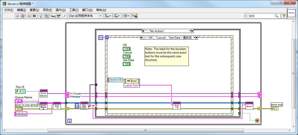 | |
| Working Principle | This is a classic state machine structure using a queue to log messages and control state transitions. The selection structure picks a branch based on each incoming message. There's a special "No Action" state for when there are no messages, leading into this branch which contains an event structure to handle UI operations. | Utilizes events (both LabVIEW-built and user-defined) to control program operations and jump between branches. The event structure includes a special "User Event" branch for all non-UI events, with an internal selection structure to handle different events. It's possible to define a user event for every processing branch, eliminating the need for a selection structure, but defining too many events can be cumbersome and make the program cluttered. A unified user event, differentiating specific events based on incoming data, makes the program more streamlined and easier to understand. |
| Development History | Early versions of LabVIEW didn't have event structures, making the state machine the most powerful interface program model. The structure shown evolved from the state machine and is one of many similar structures. The version shown here is from the official LabVIEW community by NI system engineers. | This structure evolved from the author’s continuous improvements during programming. When the author began writing interface programs, LabVIEW already had event structures. Thus, instead of following the state machine convention, the author chose a more straightforward design approach for interface programs. |
| Encapsulation | This architecture is complex, containing multiple subVIs for managing the message queue (creation, destruction, enqueueing, dequeueing, etc.). While pre-written subVIs and templates are available online, they can be somewhat complex to utilize. | LabVIEW's built-in event handling functions are simpler and can be used directly without further encapsulation. However, to streamline the program, the author further encapsulated it, placing major functionalities in a few subVIs. Some LabVIEW dialog boxes are written using this structure, so the event-related subVIs used in the program are included with LabVIEW and are readily available without downloading. |
| Code Readability, Maintainability, Scalability | More connections and subVIs increase program complexity, negatively impacting these metrics. Additionally, the primary task of interface programs is to respond to UI events, with other tasks being secondary. This architecture places the main object inside a branch of a secondary object, making it counterintuitive. | Fewer connections and subVIs lower program complexity, enhancing these metrics. |
| Adjusting Unprocessed Tasks | As the messages controlling the program's flow are managed by the user, there's flexibility. Users can adjust unhandled messages anytime, like deleting or rearranging them. However, such applications are quite rare. | Event management is internal to LabVIEW, and users cannot adjust it. |
| Control of Program Flow by Other VIs | Other VIs can insert new messages into the queue, controlling the main VI's operation. A key advantage of queues is accessing them by name without needing to connect their data lines, simplifying some programming aspects. | Other VIs can also trigger events to control the main VI's operation. Compared to queue messages, events have an additional advantage: once triggered, any VI can receive them. Thus, other VIs can control and monitor events emitted by the main VI. The drawback of events compared to queues is that they can't be accessed by name and must be connected via data lines (or use global variables). |
| Using Event Structures for Timing | In this mode, the event structure's timeout setting serves a specific purpose: setting a 100–300ms timeout event is necessary. Without this timeout event, the program might get blocked in the event structure, losing responsiveness to other state transitions. Therefore, the timeout event cannot be used for timing. | Any user event triggers the event structure, avoiding blocking issues. If the program has timing needs (like data collection every second), the timeout event can be used as a timer. |
| Latency in State Transitions | Each time the program reaches the event structure, it must wait 100–300ms for the timeout event before proceeding. If new messages are added to the queue at this time, the program won't respond immediately. | There's no issue with response latency. |
| Suitability | Suitable for various scenarios, especially when needing to flexibly change the order of messages. | Applicable in various scenarios. |
Practice Exercise
Create a simple calculator in LabVIEW that performs basic arithmetic operations like addition, subtraction, multiplication, and division. The user interface should closely resemble a basic calculator with buttons for numbers and operations.
- Front Panel:
- A numeric indicator to display the input and result.
- Buttons for digits 0-9.
- Buttons for basic arithmetic operations: addition (+), subtraction (-), multiplication (×), and division (÷).
- An "Equals" (=) button for computing the result.
- A "Clear" (C) button to reset the input.
- Block Diagram:
- Create event structures for each button to handle the input and arithmetic operations.
- Implement the logic for arithmetic operations.
- Handle the display of numbers and results in the numeric indicator.